Description
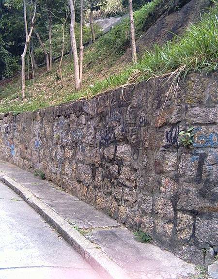
Mass concrete, stone and masonry walls are possibly the oldest form of retaining structures. They are found in archaeological sites from all ages round the world. They punctuate the landscape to the extent that they often go unnoticed (Figures 1 and 2).

(source. www.travel.webshot.com)
Masonry walls are made with bricks, blocks, natural or manufactured stones conventionally bedded with mortar, but are otherwise similar to mass concrete walls; all these walls are built on a mass or reinforced concrete foundations; they can be provided with fins or reveals to improve their overturning resistances and may be built conveniently to curves and irregular plan forms.
BS 8002 Clause 4.2.4 suggests that the simple stem walls are suitable for retaining heights up to 1.5 m while greater heights can be accommodated by stepped or buttressed walls.
In order to avoid water saturation and possible frost damage, masonry walls shall be provided with protective measures (coping, drainage, damp-proof courses and water-proofing, see for example BS 5628-Part 3, 1985) and frost resistant mortar, bricks, blocks or stones.
Masonry walls are constructed in panels, typically 10 to 15 m in length between joints; joints should be detailed in such a way to prevent unattractive vertical lines of seepage in the wall face. Panels of this length may require horizontal reinforcement. Backfill can be placed only when mortar has had time to gain appropriate strength. Durability is addressed in BS 5628 and Thomas (1996); particular attention should be paid to sulphate attack.
Masonry walls can be provided with decoration. Examples are shown in the “Brick Development Association publication by Haseltine and Tutt (1991).
Design methods
The wall specification should stipulate the materials to be considered for filling behind the wall.
The properties of the backfill will depend on whether or not locally-won backfill is to be used, and if the material is required to be free-draining. Optimum backfill is: easy to compact, giving high strength and stiffness; and free-draining, to minimize the build-up of groundwater pressure. Backfill should not include: natural or contaminated soil which will be chemically aggressive; frozen materials; degradable materials such as topsoil, peat, wood, vegetation, etc.; materials which could be toxic, dangerous or prone to spontaneous combustion; soluble material or collapsible soils. The use of clays prone to swelling should be carefully considered as they can exert very high pressures on the back of retaining walls; the same applies for materials derived from argillaceous rocks such as shales and mudstones.
These walls should be designed as gravity mass walls (see for example BS 8002; BS 5628; Geotechnical Engineering Office, 1993 and Chapman et al., 2000). By far the most common form of masonry wall is the simple brick wall; the design of unreinforced brickwork retaining walls is addressed by Haseltine and Tutt (1991).
Thomas (1996) gives guidance on the design and specification of all types of masonry walls, giving details from relevant standards.
Walls design shall put special consideration on aspects related to water pressure and drainage. Rationale and details for drainage systems can be found for example in Geotechnical Engineering Office (1993) and Chapman et al. (2000).
Special attention is also required in the design, construction and maintenance of masonry walls in seismic areas, since earthquake shaking can induce internal failure besides the global mechanisms that are normally considered in design (Figure 3 and 4).


The following ultimate limit states (ULS) need to be verified:
-
Bearing resistance failure at the base of the wall;
-
Sliding failure at the base of the wall;
-
Failure by toppling of the wall;
-
Loss of overall stability around the wall;
-
Overall stability of the slope, including the wall;
-
Unacceptable leakage beneath the wall;
-
Unacceptable transport of soil grains beneath the wall;
-
Internal stability. This aspect is covered by BS 5628 parts 1 and 2, and simple design rules are given by Haseltine and Tutt (1991); walls should be designed to resist overturning; buttresses and fins can be used to provide resistance in circumstances where their use would not conflict with other requirements.
Functional suitability criteria
Type of movement |
||
| Descriptor | Rating | Notes |
|---|---|---|
| Fall | 0 | Only suited to rotational or pseudo-rotational slides which are fully stabilized with no further movement |
| Topple | 0 | |
| Slide | 7 | |
| Spread | 0 | |
| Flow | 0 | |
Material type |
||
| Descriptor | Rating | Notes |
|---|---|---|
| Earth | 9 | Mainly applicable to landslides involving earth and debris. Applicability in rock limited by typical slope geometry and failure mode |
| Debris | 7 | |
| Rock | 4 | |
Depth of movement |
||
| Descriptor | Rating | Notes |
|---|---|---|
| Surficial (< 0.5 m) | 0 | Typically applicable to shallow landslides, fully stabilized. |
| Shallow (0.5 to 3 m) | 9 | |
| Medium (3 to 8 m) | 6 | |
| Deep (8 to 15 m) | 0 | |
| Very deep (> 15 m) | 0 | |
Rate of movement |
||
| Descriptor | Rating | Notes |
|---|---|---|
| Moderate to fast | 0 | Should be carried out preferably on very or extremely slow landslides which become fully stabilized. |
| Slow | 0 | |
| Very slow | 7 | |
| Extremely slow | 8 | |
Ground water conditions |
||
| Descriptor | Rating | Notes |
|---|---|---|
| Artesian | 8 | Applicable in all groundwater conditions. Adequate drainage must be provided to wall and at the interface between low permeability backfills, if any, and natural soil |
| High | 8 | |
| Low | 7 | |
| Absent | 9 | |
Surface water |
||
| Descriptor | Rating | Notes |
|---|---|---|
| Rain | 6 | Applicable in contact with watercourses, but construction requires temporary diversion/exclusion and foundations must be protected against scour. |
| Snowmelt | 6 | |
| Localized | 5 | |
| Stream | 5 | |
| Torrent | 4 | |
| River | 5 | |
Reliability and feasibility criteria
| Criteria | Rating | Notes |
|---|---|---|
| Reliability | 6 | Reliability penalized by susceptibility to loss of integrity on further movement. |
| Feasibility and Manageability | 8 | Relatively simple technique, Potential benefits and limits of applicability are well established. |
Urgency and consequence suitability
| Criteria | Rating | Notes |
|---|---|---|
| Timeliness of implementation | 8 | Downgrade to 6 where work involves heavy lifting using cranes in confined workplaces or on steep slopes |
| Environmental suitability | 4 | will be updated |
| Economic suitability (cost) | 8 | Low to moderate, provided the work does not involve diversion of major water courses or interference with existing infrastructure. |
References
-
BS 8002 (1994) ”Code of Practice for Earth Retaining Structures”.
-
BS 5628, Part 1 (1992) ”Code of practice for use of masonry - Structural use of unreinforced masonry”.
-
BS 5628, Part 2 (1995) ”Code of practice for use of masonry - Structural use of reinforced and prestressed masonry”.
-
BS 5628, Part 3 (1985) ”Code of practice for use of masonry - Materials and components, design and workmanship”.
-
Chapman T., Taylor H., Nicholson D. (2000). “Modular Gravity Retaining Walls – Design Guidance”. Publication C516, CIRIA, London.
-
Geotechnical Engineering Office (1993) ”Geoguide 1 – Guide to Retaining Wall Design” Civil Engineering Department, The Government of the Hong Kong, Special Administrative Region.
-
Haseltine B.A., Tutt J.N. (1991) ” The design of brickwark retaining walls” The Brick Development Association Design Guide n° 2, revised edition.
-
Thomas K. (1996) ”Masonry walls, specification and design” Butterworth Heinemann.