Description
Soil nailing is the insertion of solid or hollow steel or glass fibre bars into the face of an excavation or an existing slope to reinforce it, transferring part of the load from the potentially unstable mass to more competent strata, typically where the potentially unstable mass has a maximum thickness of 6 to 8 m. The face of the slope is protected by shotcrete and welded wire mesh, geogrid/geotextiles sheets and cast-in-place concrete or prefabricated panels.
The technique has been developed in France, Germany and United States over the past 25 years or so (Guilloux and Schlosser, 1985; Nicholson, 1986; Bruce and Jewell 1986a; 1986b; Munfach et al.; 1987; Juran and Elias, 1987; Gnilsen, 1988, Recommendations Clouterre, 1991; Byrne et al., 1998; Mitchell and Jardine, 2002; Phear et al., 2005), as a development of the “root piles” technique originally developed in the 1950’s described by Lizzi (1977); Bruce (1992a, b). Its application has extended to a wide variety of ground types, from soils to weathered and un-weathered rocks; while the term “ground nail” might be a more suitable generic term, “soil nail” has become established as the commonly accepted generic terminology and is used here for nails installed in all types of ground which can be conveniently described as continuoum. Case histories are listed for example in Bruce and Jewell (1987a; 1987b) and Bruce (1989).
A typical construction sequence for drilled and grouted nails is described below and shown in Figure 1; alternative methods of installations include percussive methods or vibro-drilling (Myles and Bridle, 1991), combinations of vibration driving with injections and driving nails by compressed air or pyrotechnic launchers A typical application is shown in Figure 2.
-
Installation of ditches to intercept and divert surface water; exacavation/trimming in stages of limited height (typically 1 or 2 m), minimizing ground disturbance and removing loosened areas, leaving a working bench of 5÷7 m width. For installation in existing slopes, special provision must be made for access (long reach booms, sledges or similar).
-
Dilling of nail holes at predetermined locations to a specified length and inclination using drilling methods appropriate for the ground, supporting the drillhole with casing, if required, although this will often have serious adverse impact on the cost effectiveness of soil nailing. Bentonite or other mud suspensions should not be used, as “smear” on the drillhole walls can significantly reduce the grout-to-ground bond. Typical drillhole size: 100 to 300 mm; spacing: 1 to 2 m, both vertically and horizontally; inclination: 15° below horizontal to facilitate grouting; length: 6 to 15 m (up to 28 m using large hydraulic-powered track-mounted rigs with continuous flight augers).
-
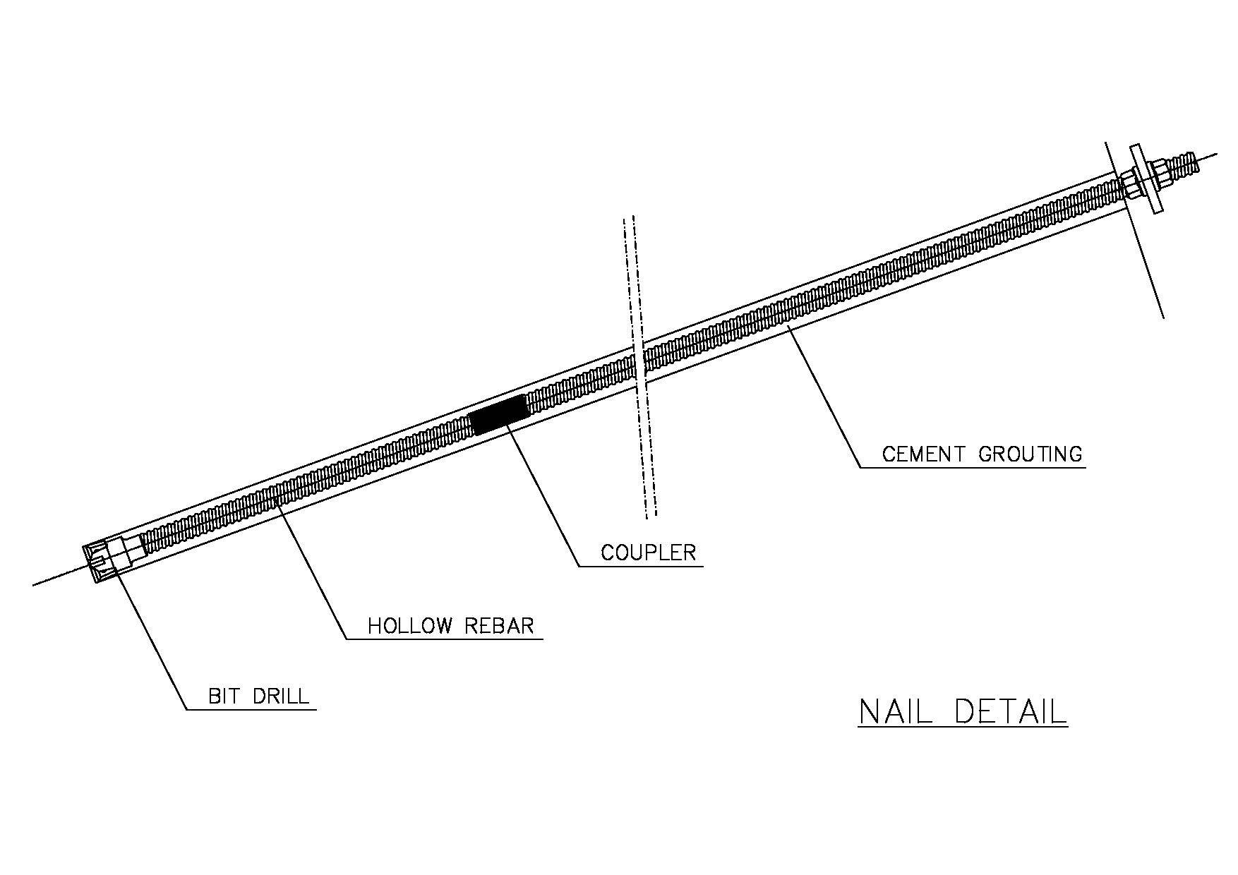
Installation and grouting of nails. Plastic or steel centralizers are commonly used to center the nail in the drillhole; stiffer grout mix may be alternatively used to maintain the position of the nail and prevent it from sinking to the bottom of the hole. The steel nails are commonly 25 to 50 mm in diameter; solid or hollow; the yield strength is 420 to 500 N/mm2. Steel nail diameter smaller than 25 mm are not recommended due to difficulties associated with placement of such flexible tendons in drilled holes. Grouting takes place under gravity or low pressure from the bottom of the hole upwards. Grouted steel nails protected only by the grout annulus are not generally considered adequate for permanent application in some countries; in this cases, additional protection against corrosion may be given by sacrificial thickness, by heavy epoxy coating and by encapsulating it in a grout-filled corrugated plastic sheathing. “Self-drilling nails” (Figure 3) can be used where open hole drilling is not possible or practical. However, they require special corrosion considerations and testing procedures to be considered for permanent applications. In general the self-drilling nails should not be used in aggressive ground (as defined in Byrne et al., 1998) and coatings should not be considered acceptable corrosion protection, which can be assured only by providing sacrificial steel.
-
Placement of drainage system and installation of the construction facing and of the bearing plates. Prefabricated synthetic drainage mats are placed in vertical strips (about 400 mm wide) between the nail heads at horizontal spacing equal to that of the nails. The drainage strips are extended down to the base of the structure and connected either directly to a footing drain or to weep holes that penetrate the final wall facing. If water is encountered, short horizontal drains are generally required to intercept the water before it reaches the face. The construction facing typically consists of a mesh-reinforced shotcrete layer of the order of 100 mm thick. Following placement of the shotcrete a steel bearing plate (typically 200 mm x 250 mm square and 20 mm thick) and securing nut are placed at each nail head and the nut is hand wrench tightened sufficiently to embed the plate a small distance into the still plastic shotcrete.
-
Progressive construction to the final grade. In excavation or on large slopes, the process described at steps 1 to 4 is repeated in stages to the final grade. The maximum bench height and construction sequence must be verified carefully, to ensure stability at all stages of construction.
-
Final facing. For long term structural durability, a concrete facing or a second layer of shotcrete is finally applied on the exposed surface. Rip rap or biotechnological finishes also applied, especially in landslide stabilization works.
|
STEP 1 Install cut-off drainage and excavate unsupported cut, 1 to 2 m high |
|
|
|
STEP 2 Drill hole for Nail |
|
|
|
STEP 3 Install and grout Nail |
|
|
|
STEP 4 Place drainage strips, initial shotcrete layer and bearing plates and nuts |
|
|
|
STEP 5 Repeat process to Final Grade |
|
|
|
STEP 6 Place Final Facing (on permanent walls) |
|
|


In case of permanent reinforcement and use of drilling and grouting methods, the steel bar is encapsulated in a cement grouted body to provide corrosion protection and improved load-transfer to the soil; the steel bar is also typically protected with a heavy epoxy coating or by encapsulation in a grout-filled corrugated plastic sheathing. For other installation methods protection against corrosion can be provided by sacrificial thicknesses; BS 8006:1995 gives guidance on sacrificial thicknesses for galvanized and non-galvanised nails. When shotcrete facing is not adopted, corrosion protection at the nail head may be provided by precat or cast-in-place concrete head details.
Nails are characterized by “continuous” reinforcement with transfer of shear stress along the full length of the inclusion. The effect is to reduce nail forces at the face, allowing the use of only a thin cover, primarily to resist erosion or slump of the face.
The nails are installed horizontally or suborizontally, approximately parallel to the direction of major tensile straining in the soil. The nails work predominantly in tension, but are considered to work also in bending/shear, especially where the orientation is perpendicular to the anticipated shear surface; in these cases nails may more properly be called dowels.
The nails contribute to the support of the soil partially by directly resisting the destabilizing forces and partially by increasing the normal loads (and hence the shear strength) on potential sliding surfaces (see Figure 3 of fact sheet 6.0 on the general aspects of hazard mitigation by transfer of load to more competent strata). The reinforcements are passive and develop their action through nail-soil interaction as the soil deforms; the face protection need to be installed in order to keep the soil from caving in between the bars.
The reinforced soil body (nails plus face protection) becomes the primary structural element; in fact, the reinforced zone performes as a homogeneous resistant unit to support the unreinforced soil behind it in a manner similar to a gravity wall. (Stocker et al., 1979).
The technique offers several advantages:
-
Construction flexibility in heterogeneous soils with cobbles, boulder and other hard inclusions, as the obstructions offer no problems for the relatively small diameter nail drillholes.
-
Well suited to sites with difficult or remote access because of the relatively small size and mobility of the equipments.
-
High system redundancy as the soil nails are installed at high density and the consequence of a unit failure are therefore correspondingly less severe.
-
The system is relatively robust and flexible and can accommodate significant total and differential displacements.
-
Soil nailing has been documented to perform well under seismic loading conditions (See for example Felio et al., 1990).
-
Additional nails can easily be installed during construction, if slope movements occur or is greater than expected.
-
The method is well suited for rehabilitation of distressed retaining syructures.
The disadvantages of the technique are mainly linked to its constructability, in relation to nature of ground to be reinforced and/or presence of groaundwater percolating through the face; in general, the economical use of soil nailing requires that the ground be able to stand during construction. In addition, when the drill and grout methods is adopted, it is highly desirable that the open drillhole can maintain its stability for at least several hours. Therefore difficulties can be experienced in:
-
Loose clean sands and gravels or coarse grained soils of uniform size unless in a very dense condition; these soils will not generally exhibit adequate stand-up time and are also sensitive to vibration induced by construction equipments.
-
Soils with excessive water content or below the groundwater; significant groundwater seepage at the exposed face can cause serious problems (e.g. local slump; drillhole instability, impossibility to obtain a satisfactory ground-grout bond).
-
Organic soils or clayey soils with Liquidity Index greater than 0.2 and undrained shear strength less than 50 kPa; remoulding caused by nail installation in may reduce skin friction to unacceptable values.
-
Higly fractured rocks with open joints or voids and open graded coarse materials (e.g. cobbles), geotextile nail socks or low slump grout may be necessary in such materials to mitigate the difficulty of satisfactorily grouting the nails.
-
Rock or decomposed rock with weak structural discontinuities inclined steeply toward and daylighting into the cut face.
-
Expansive (e.g. swelling) soils; these soils may result in significant increases in the nail loading near the face. Water must be prevented from reaching expansive soils that are soil nailed.
It should also be noted that the long-term performance of shotcrete facings has not been fully demonstrated, particularly in areas subjected to freeze-thaw cycles. In these circumstances it is recommended that the design prevents frost from penetrating the soil by provision of an appropriate protective structure (e.g. granular or synthetic insulating layer).
Special attention must be paid in both the design and the construction stage to the issue of corrosion and durability of the structural elements. For further guidance on this issue, reference may be made to Recommendations Clouterre (1991), Phear et al. (2002) and Byrne et al. (1998), who also provides detailed recommendations on drainage and frost protection.
Design methods
As highlighted by Mitchell and Jardine (2002), there is still much discussion about the assessment of the behavior and stability of nailed structures. A discussion on the differences between the design approaches widely used in Europe and the United States, as reported in Schlosser (1983) and Juran and Beech (1984), can be found in Juran and Elias (1987), Gnilsen (1988), Jewell (1990), Jewell and Pedley (1990a; 1990b; 1990c; 1991), Bridle and Barr (1990) and Schlosser (1991).
Solutions to the problem require:
-
Carrying out appropriate soil structure interaction analyses to investigate the internal stability of the composite system made up by nails, facing and soil, both in the “active zone” close to the facing, where the shear stresses exterted by the soil on the reinforcement are directed outward and tend to pull the reinforcement out of the ground, and in the “resistant zone”, where the shear stresses are directed inward and tend to restrain the reinforcement from pulling out.
-
Evaluation of the overall stability of the nailed structure, considered as a massive retaining structure (external stability).
For internal stability to be achieved, the nail tensile strength must be adequate to provide the support force to stabilize the active block. The nails must also be embedded a sufficient length into the resistant zone to prevent a pullout failure.
In addition, the combined effect of the nail head strength (as determined by the strength of the facing or connection system) and the pullout resistance of the length of the nail between the face and the slip surface must be adequate to provide the required nail tension at the slip surface (interface between active and resistant zones).
All potential failure modes, which involve: a) face failure (active zone slides off the front of nails); b) pullout of nails from the resistant zone; c) structural failure of nails (in tension, bending or shear), must be analysed separately (simplified procedures) or simultaneously (advanced approaches).
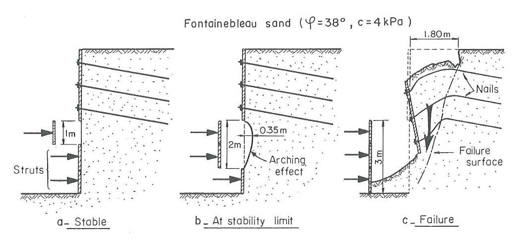
Major difficulties in finding rigorous and reliable solutions for the internal stability of the nailed structure derive from the fact that both the forces acting in the nails and the forces acting on the facing are governed by the deformation behavior of the entire system, which, in turn, depends on the geometric and mechanical characteristics of the various elements (including the soil), together with the sequence, rate and method of construction. For example, the latter may influence the load transfer characteristics between soil and nail. The building of soil nailed structure involve a critical phase with respect to internal or external stability, which can be lower during the building phase than when the reinforcement is finally built. Therefore, internal and external stability of the nailed structure shall be checked for all the construction phases (Figure 4).
The simplest and most widely adopted method to investigate both internal and external stability of soil nailed structures is based on the slip surface limit equilibrium method by incorporating the reinforcing effect of the nails, including consideration of the strength of the nail head connection to the facing, the strength of the nail tendon itself and the pullout resistance of the nail-ground interface. Typically, the analyses are carried out with reference to Ultimate Limit States, with the magnitude of deformations (Servicibility Limit States) controlled indirectly by application of appropriate values of partial factors in ULS calculations. Where deformations are critical, it becomes necessary to resort to numerical analyses.
The contribution of any nail to the stability of a particular sliding surface will be the least of a) the tensile strength (shear/bending contributions neglected) or the “ideal” strength (shear/bending contributions considered) of the nail; b) the pullout resistance of the length of nail beyond the slip surface; c) the nail head strength plus the pullout resistance of the length of nail between the slip surface and the face of the exposed surface. All potential surfaces must be examined to ensure that the design is complete.
The potential contribution of shear and/or bending of the nails to the overall resistance of the system is typically negligible and in any case difficult to evaluate, with different procedures being proposed in the literature (Schlosser, 1982; Schlosser, 1983; Blondeau et al., 1984; Jewell and Pedley, 1990a, b; Juran et al. 1990; Schlosser, 1991). Experimental studies (for example Jewell and Pedley, 1990a, b) have shown that this contribution is less than 10% of that provided by tensile forces and is only achieved after large displacements, as also stated by Gässler (1990).
In case of drill and grout method of nail installation, the pullout resistance of the nail will be the least of ground-grout bond and grout-tendon bond. Ground-grout bond is strongly dependent on the method of construction; for this reason both pullout tests and short-term creep tests are a standard part of nail preliminary testing for check and calibration of the design before starting with the construction activities; in short-term creep tests, the rate of creep of the nail will increase as the applied load increases; a creep rate exceeding 6 mm/60 minutes is generally considered unacceptable (see for example Byrne et al., 1998).
For preliminary design evaluation of ground-grout bond, reference can be made for example to Bustamente and Doix (1985). More generally, reference may be made to the charts proposed by Recommendation Clouterre (1991) which relate pullout resistance to the type of soil and the method of installation, subject always to verification by pullout tests in the field.
Pullout tests can also be carried out in the laboratory, but the boundary conditions of the apparatus and the idealization of the field conditions mean that the results from such tests are not always realistic.
In case of continuous threadbars, grout-tendon bond is typically an order of magnitude or more higher than the ground-grout bond and is therefore not critical for soil nailing applications when proper grout mix and installation techniques are used.
The strength of the nail head may be controlled by the flexural and punchning shear strength of the facing; these strengths are usually determined by specific structural analyses, taking into account the grid layout of the nails; some examples are given by Byrne et al. (1998) and by Phear et al. (2005). Other potential failure mechanisms do exist for the nail head; however,
these modes will not usually control the design or limit the nail head strength for the types of systems commonly employed in soil nail structure construction. For discontinuous facing elements, the face plate should be checked against bearing failure (see DoT Advice Note HA 68/94, 1994 for guidance). External stability refers to the potential deformation modes typically associated with gravity or cantilever retaining structures and involves considerations of:
-
Horizontal sliding and/or overturning under the lateral earth pressure of the ground retained behind the reinforced mass.
-
Bearing capacity failure under the combined effect of self weight and lateral earth pressure loading.
-
Overal slope stability of the ground on which the soil nailed structure is located.
In the simplified procedure, both internal and external stability analyses are usually carried out in 2D (plane strain) conditions.
In order to check both stability and deformation behaviour of the soil nailed structure the analyses carried out with the simplified procedure can be supplemented by true soil-nail-facing interation analyses with the use of finite element (FE) methods; the best approach is to use 3D models, where the nail is modelled explicitly as is; often the 3D geometry is such that it can be simplified considering symmetry in the model.
In static conditions, the reliability of the design method depends on the correct selection of the operational strength parameters of the soil and on the correct modelling of the ground-grout load transfer curves; uncertainties can be minimized by preliminary pull-out tests.
The internal and external stability under seismic conditions can be investigated by means of pseudo-static methods and/or finite element methods; the external stability can be also investigated by means of Newmark type of analysis. The reliability of pseudo-static analyses depends on the same factors affecting static analyses, with the addition of uncertainties on the appropriate values of pseudo-static seismic coefficient kh to be used; Newmark type analyses must be carried out for a large number of strong motion records and the results must be treated by statistical techniques to minimize error.
FEM analyses retain all the limitations of the simpler methods, except that they can incorporate a more detailed constitutive modelling of soil behaviour, overcoming the need to preselect operational values of strength, as well as geometric simplifications.
Systematic monitoring and reporting of performance is necessary, both to verify that the structure performs as anticipated and to enhance confidence and expertise in the use of this technique in the future, especially in light of continuing debate on the best methods of design. In particular, monitoring of any lateral outward movement of the face is highly desirable. Designers should detail monitoring requirements (type, location, frequency and data treatment) as an integral part of the design.
Performance monitoring instrumentation should include slope inclinometers, survey points and nail loads at the head and along the nail length to measure movements and stresses during and after construction.
Sufficient environmental monitoring should also be carried out to provide the necessary framework for interpretation of performance monitoring. Environmental monitoring should include, as a minimum, temperatuire variations and groundwater levels.
Monitoring should continue for a period of at least 2 years after construction, in order to gather information as a function of time and environmental changes such as freeze-thaw cycles and/or variations in groundwater levels.
For further details on the design of soil nailing stuctures, reference may made to the guidelines published in France (Recommendation Clouterre, 1991); the United Kingdom (DoT, 1994; BSI, 1995; Phear et al., 2005) and the United States (Byrne et al., 1998; Lazarte et al., 2003).
Functional suitability criteria
Type of movement |
||
| Descriptor | Rating | Notes |
|---|---|---|
| Fall | 7 | Applicable to slides and in special circumstances to falls and topples in cemented or stiff/hard cohesive soils. |
| Topple | 6 | |
| Slide | 8 | |
| Spread | 0 | |
| Flow | 0 | |
Material type |
||
| Descriptor | Rating | Notes |
|---|---|---|
| Earth | 9 | Applicable to earth and debris. In very coarse debris drilling can be problematical and launching is precluded. |
| Debris | 5 | |
| Rock | 0 | |
Depth of movement |
||
| Descriptor | Rating | Notes |
|---|---|---|
| Surficial (< 0.5 m) | 8 | Practical soil nail lengths and the need to achieve sufficient anchorage in the underlying stable soil limit the application of this technique to situations where the residual thickness of the actual or potential landslide to be stabilized is significant. |
| Shallow (0.5 to 3 m) | 9 | |
| Medium (3 to 8 m) | 7 | |
| Deep (8 to 15 m) | 0 | |
| Very deep (> 15 m) | 1 | |
Rate of movement |
||
| Descriptor | Rating | Notes |
|---|---|---|
| Moderate to fast | 0 | Workers’ safety and end result require construction to take place when movement is extremely slow or very slow (maximum 1.5 m/year, corresponding to approximately 5 mm/day). Under special conditions and taking due precautions it may be carried out when movement is ”slow” (up to 1.5 m/month, corresponding to 5 cm/day) . |
| Slow | 2 | |
| Very slow | 9 | |
| Extremely slow | 10 | |
Ground water conditions |
||
| Descriptor | Rating | Notes |
|---|---|---|
| Artesian | 0 | Drillhole stability where groundwater may be encountered should be reviewed carefully, since the use of temporary casing, if required, would normally make this technique excessively expensive. Groundwater seepage at the surface must be avoided, incorporating suitable drainage works, with the risk of local slumping before the draingae works are effective. |
| High | 2 | |
| Low | 4 | |
| Absent | 10 | |
Surface water |
||
| Descriptor | Rating | Notes |
|---|---|---|
| Rain | 8 | Where sliding is due to channelized water, construction difficulties may be expected and there may be special requirements for the facing. |
| Snowmelt | 7 | |
| Localized | 5 | |
| Stream | 3 | |
| Torrent | 0 | |
| River | 1 | |
Reliability and feasibility criteria
| Criteria | Rating | Notes |
|---|---|---|
| Reliability | 6 | Successful application depends on correct schematization and characterization of the landslide, design and construction detail, correct application. |
| Feasibility and Manageability | 6 | There is over 25 years experience with the technique, but it is still susceptible to technological and design improvements. |
Urgency and consequence suitability
| Criteria | Rating | Notes |
|---|---|---|
| Timeliness of implementation | 6 | Requires specialist equipment; special arrangements may be required for access on existing slopes; simplified by launching but durability is questionable. |
| Environmental suitability | 4 | will be updated |
| Economic suitability (cost) | 6 | Moderate. Can become quite high if drillholes require temporary casing and/or special access arrangements. |
References
-
Bridle R.J., Barr B.I.G. (1990). ”Discussion on Jewell & Pedley (1990b)” Ground Engineering, vol.23, n° 6, 30-31.
-
Bruce D.A. (1989). American developments in the use of small diameter inserts as piles and in situ reinforcements”. Proc. of Int. Conf. on Piling and Deep Foundations, Deep Foundations Institute, vol. 1, 11-22.
-
Bruce D.A., Jewell R.A. (1986). ”Soil nailing: application and practices, Part 1”. Ground Engineering, vol. 19, n° 8, 10-15 .
-
Bruce D.A., Jewell R.A. (1987a). ”Soil nailing: application and practices, Part 2”. Ground Engineering, vol. 20, n° 1, 21-38 .
-
Bruce D.A., Jewell R.A. (1987b). ”Soil nailing: the second decade”. Proc. Int. Conf. on Foundations and Tunnels, vol. 2, 68-83.
-
Bruce D.A. (1992a). ”Recent progress in American pinpile technology”. Proceeedings of a Conference on grouting, soil improvement, and geosynthetics, New Orleans, R.H. Borden, R.D. Holtz, I. Juran editors, Geotechnical special Publication 30, ASCE, 2, 765-777.
-
Bruce D.A. (1992b). ”Two new specialty geotechnical processes for slope stabilization”. Proceedings of a specialty Conference on stability and performance of slopes and embankments, Berkley, CA, R.B. Seed and R.W. Boulanger editors, Geotechnical Special Publication 31, ASCE, 1505-1519.
-
BS 8006: 1995 ”Code of practice for strengthened-reinforced soils and other fills”. British Standard Institute.
-
Bustamente M., Doix B. (1985). ”Une méthode pour le calcul des tirants et des micropieux injectés”. Bull. Liaison labo P. Et Ch., 140, ref. 3047, 75-92.
-
Byrne R.J., Cotton D., Porterfield J., Wolschlag C., Ueblacker G. (1998). ”Manual for Design & Construction Monitoring of Soil Nail Walls”. U.S. Department of Transportation, Federal Highway Aministration, Publication n° FHWA-SA-96-069R, Revised October 1998.
-
Gässler, G. (1990). “In situ techniques of reinforced soil. State of the art report”. Proc. BGS Conference on Performance of Reinforced Soil Structures, Glasgow, Thomas Telford, London, 185-196.
-
Gnilsen R. (1988). ”Soil nailing debate”. Civil Engineering, ASCE, vol. 58, n° 8, 61-64.
-
Guilloux A., Schlosser F. (1985). ”Soil nailing: practical applications”. Proc. of Int. Symposium on Recent Developments in Ground Improvement Techniques, Bangkok, Balkema, 289-297.
-
Felio G.Y., Vucetic M., Hudson M., Barar P., Chapman R. (1990). ”Performance of soil nailed walls during the October 17, 1989 Loma Prieta earthquake”. Proc. of 43th Canadian Geotechnical Conference, Quebec, Canada.
-
DoT (1994). ”Advice Note HA 69/94. Design methods for the reinforcment of highway slopes by reinforced soil and soil nailing techniques.”. design manual of Roads and Bridges, vol. 4, sect. 1, part 4, The Highway Agency, HMSO, UK
-
Jewell R.A. (1990). ”Review of theoretical models for soil nailing” Proc. of Int. Conf. on Performance of reinforced soil structures, A. Mc Gown, K.C. Yeo, K.Z. Andrawes editors, Thomas Telford, 265-275.
-
Juran I., Beech J. (1984). ”Theoretical analysis of the behaviour of nailed soil retaining structures” Proc. of Int. Con. on In-Situ Soil and Rock Reinforcement, Paris, 301-307.
-
Juran I., Elias V. (1987). ”Soil nailed retaining structure. Analysis of case histories”. Proc. Spec. Conf. on Soil Improvement – a ten year update, J.P. Welsh editor, ASCE, Special Publication 12, 232-244.
-
Jewell R.A., Pedley M.J. (1990a). ”Soil nailing design – the role of bending stiffness”. Report n° OUL 1813/90, Department of Engineering Science, University of Oxford.
-
Jewell R.A., Pedley M.J. (1990b). ”Soil nailing design – the role of bending stiffness”. Ground Engineering, vol.23, n° 2, 30-36.
-
Jewell R.A., Pedley M.J. (1990c). ”Replay to discussion by Bridle & Barr (1990)”. Ground Engineering, vol.23, n° 6, 32-33.
-
Jewell R.A., Pedley M.J. (1991). ”Closure to discussion by Schlosser (1991)”. Ground Engineering; vol. 24 n° 9, 34-39.
-
Juran I., Baudrand G., Farrag K., Elias V. (1990). ”Kinematical limit analysis for design of soil nailed structures”. Journal of Geotechnical Engineering, ASCE, 116, 1, 54-72
-
Lazarte C.A., Elias V., Espinoza D., Sabatini I.J. (2003). ”Geotechnical Circular n. 7, Soil Nail Walls”. US Department of Transportation, FHWA, FHWA-A0-IF-03-017, Washington D.C. (http://isddc.dot.gov/OLPFiles/FHWA/016917.pdf )
-
Lizzi F. (1977). ”Practical engineering in structurally complex formations (the In Sity Reinforced Earth) ”. Proceedings International Symposium on the Geotechnics of Structurally Complex Formations, Capri, Italy, AGI.
-
Mitchell J.M., Jardine F.M. (2002). ”A guide to ground treatment”. CIRIA C573, London.
-
Munfakh G.A., Abramson L.W., Barksdale R.D., Juran I. (1987). ”In-situ ground reinforcement”. Proc. Spec. Conf. on Soil Improvement – a ten year update, J.P. Welsh editor, ASCE, Special Publication 12.
-
Myles B., Bridle R.J. (1991). ”Fixed soil nails – the machine”. Ground Engineering, vol. 24, n° 6, 38-39.
-
Nicholson P.J. (1986). ”In situ ground reinforcement techniques”. Proc. Int. Conf. Deep Foundations, Deep Foundations Institute and CIGIS, Beijing, China.
-
Phear A., Dew C., Ozsoy B., Wharmby N.J., Judge J., Barley A.D. (2005). ”Soil nailing – best practice guidance”. CIRIA C637.
-
Recommendation Clouterre (1991). ”Designing, calculating, constructing and inspecting earth supported systems using soil nailing”. French National Research Project Clouterre, Ponts et Chausséès Press, U.S. Department of Transportation, Federal Highway Administration, English translation 1993.
-
Schlosser F. (1982). ”Behaviour and design of soil nailing”. Symposium on recent developments in ground improvement techniques, Bangkok, 399-413.
-
Schlosser F. (1983). ”Analogies and différences dans le comportement et le calcul des ouvrages de soutènement en terre armée et par clouage du sol”. Annales ITBTP, n° 418, Sols et Foundations 184, October, 8-23
-
Schlosser F. (1985). ”Behaviour and design of soil nailing”. Proc. Int. Symposium on Recent Developments in Ground Improvement Techniques, Bangkok, Balkema, 399-413.
-
Schlosser F. (1991). ”Discussion on Jewell & Pedley (1990b)” Ground Engineering, vol. 24, n° 9, 30-33.
-
Stocker M.F., Korber G.W., Gassler G., Gudheus G. (1979). ”Soil nailing”. Proc. Int. Conf. on Soil Reinforcement, Paris, vol. 2, 469-474.
-
Vucetic M., Trufenkjian M.R., Doroudian M (1993). ”Dynamic centrifuge testing of soil nailed excavation”. Geotechnical Testing Journal, ASTM.