Description
Horizontal drains are used to stabilize deep landslides essentially characterized by circular slip surface. They are adopted in fine-grained soils and in fissured rocks. The schematic layout of horizontal drains, represented in typical longitudinal and cross sections, are shown in Figs. 1 a, b, c (Pun & Urciuoli, 2008).

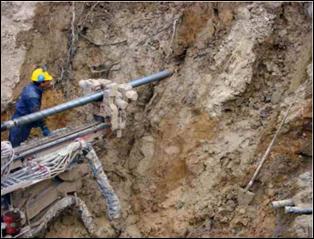
Horizontal drains involve drilling holes in the ground, drilled with a tricone or drag bit (Figs. 2, 3). The diameter of the hole is usually 100-120 mm. During drilling, flushing fluid such as bentonite mud, polymers, foam, water or air is required to reduce friction and aid the removal of the cuttings. A PVC slotted pipe, protected by a geo-textile to avoid the clogging with fine materials, is inserted in the hole (Fig. 4). The maximum length of horizontal pipes is around 100 m, but in some cases it has been possible to reach 300 m. Deposits of calcium, salts and iron oxide can block horizontal drains during operation; therefore regular maintenance by flushing the pipes with a high pressure water jet, should be programmed. In absence of maintenance, drain pipes cannot keep functioning for a long time (maximum 15-20 years). A good practice to reduce precipitation of calcite inside pipes consists of drilling the hole at an inclination slightly above horizontal, such that the pipe is not continuously submerged. Conversely, there are other chemical phenomena, favored by bacterial activity, that are due to aeration (Walker & Mohen 1987). At the portion of the horizontal drain near to the slope surface, it is recommended to use a 3-6 m long un-perforated pipe, grouted all around with cement, to prevent the penetration of tree roots into the pipe, which could block the water flow (Fig. 4). The timerequired for installation is approximately 100-200 m per day.


Design methods
The design of horizontal drains can be carried out by using numerical analyses or easily by adopting design charts available in literature (see Di Maio et al.1988, Desideri et al. 1997, Pun & Urciuoli 2008).
In the first case drainage work is analysed by means of numerical codes (DEM or FEM) and the problem may be solved by taking soil stratigraphy and heterogeneity into account and by assuming a water flux depending on the climate condition at the upper boundary. In this way, pore pressures can be calculated along the critical sliding surface; then they can be used in slope stability analysis.
In the second case, non-dimensional charts obtained for homogeneous soil and very simple geometric schemes are used to estimate pore pressure, lowered by drains. Design charts are a general tool useful for general conditions: they cannot consider hydraulic conditions at ground surface according to a seasonal trend, which necessarily depends on typical climatic features of the region. In fact the methods for analyzing the stabilization effect of drain trenches commonly available in the literature assume the presence of a film of water at the ground surface. The major use of design charts consists of obtaining the geometric configuration from the global efficiency of the drainage system that is determined as a function of the pore water distribution that guarantees the safety factor chosen by the designer.
Based on numerical analyses, Desideri et al.1998 proposed design charts for drains installed from the ground-surface, with the drain rows placed at the distance S along the maximum slope direction (if they are installed on two or more alignments); the distance along the direction normal to slope is indicated by i. L is the length of the slope where pore pressures are reduced by draining, D is the depth of the plane parallel to the ground surface on which the efficiency is evaluated, Xpd is the relative position of the drainage system respect the lower end of the longitudinal section L (Fig 5 a,b).

In the analysis, the following hypothesis are assumed:
-
infinite slope;
-
homogeneous soils and isotropic permeability;
-
presence of a film of water at the ground surface;
-
two-dimensional flow conditions (by assuming values of the ratio i/l<2);
-
constant ratio d/l=0.02;
-
flow parallel to the ground surface, as initial conditon.
Design charts have been developed by the authors for different slope angles, as a function of the ratios l/L, Xpd/L, S/L,. for one and two rows of drains. The design charts allow to obtain:
-
the optimum design of system;
-
the system efficiency;
-
the time at which 90% and 50% of efficiency is reached.
The first step of the design procedure is to determine the maximum factor of safety corresponding to the atmospheric pore pressure distribution in the subsoil and then the increment of the factor of safety (relative to its initial value) that is necessary to assure a suitable level of safe of the slope. These two values of safety factors are the ingredients for the calculation of the long-term efficiency of the drain system. The following step is to design the geometric configuration of drains that will result in the required pore pressure change. A single level of drains is assumed initially. The values of L, D, Xpd are assigned and by using Figures 6c, d, 7c, d the lenght of drains, l, and then the efficency at long term are obtained. In this way it is possible to evaluate if the efficiency of the hypothized drain system is larger than the required value. If necessary, an increase in system efficiency can be achieved by increasing the lenght of the drains, but no significant benefits are obtained for values higher than l = 4 -5 D. The values of the time factor corresponding to 50% and 90% of efficiency are obtained from Figures 6a, b, 7a, b, .


If the results do not satisfy the design problem (too long to achieve efficiency, low safety factor, etc..) a system of drains installed on two levels can be considered. A value of E∞ is fixed and l, Xpd, and S are determined by using Figures 8-9.


Functional suitability criteria
Type of movement |
||
| Descriptor | Rating | Notes |
|---|---|---|
| Fall | 2 | Horizontal drains are used to stabilize deep slides essentially characterized by circular slip surface and with a high slope angle of the ground surface. |
| Topple | 2 | |
| Slide | 6 | |
| Spread | 2 | |
| Flow | 4 | |
Material type |
||
| Descriptor | Rating | Notes |
|---|---|---|
| Earth | 4 | They are adopted in fine-grained soils and in fissured rocks as well. |
| Debris | 8 | |
| Rock | 4 | |
Depth of movement |
||
| Descriptor | Rating | Notes |
|---|---|---|
| Surficial (< 0.5 m) | 0 | The horizontal drain system is suitable for deep slip surfaces. |
| Shallow (0.5 to 3 m) | 2 | |
| Medium (3 to 8 m) | 6 | |
| Deep (8 to 15 m) | 6 | |
| Very deep (> 15 m) | 4 | |
Rate of movement |
||
| Descriptor | Rating | Notes |
|---|---|---|
| Moderate to fast | 2 | The steady-state condition is attained some time after drainage construction (i.e. at the long term) in fact after drain installation, a transient phenomenon of equalization of pore pressures occurs. Drains are completely effective after such a delay and they represent the suitable mitigation measure for very slow landslides. |
| Slow | 6 | |
| Very slow | 8 | |
| Extremely slow | 8 | |
Ground water conditions |
||
| Descriptor | Rating | Notes |
|---|---|---|
| Artesian | 4 | This system is suitable for deep freatic water table. |
| High | 6 | |
| Low | 8 | |
| Absent | 0 | |
Surface water |
||
| Descriptor | Rating | Notes |
|---|---|---|
| Rain | 4 | Horizontal drains are not suitable to drain shallow water. |
| Snowmelt | 4 | |
| Localized | 0 | |
| Stream | 0 | |
| Torrent | 0 | |
| River | 0 | |
Reliability and feasibility criteria
| Criteria | Rating | Notes |
|---|---|---|
| Reliability | 6 | Necessary to flush the pipes with high pressure water jets for good operation. The most frequent problems are: fouling, deterioration of the final collector, changing of the water path. |
| Feasibility and Manageability | 7 | Technique and design process are well established and widely used in suitable conditions. |
Urgency and consequence suitability
| Criteria | Rating | Notes |
|---|---|---|
| Timeliness of implementation | 6 | Difficult to have good installation of the pipe, especially if very long; it is good practice to drill the hole slightly inclined to allow gravity drainage. |
| Environmental suitability | 4 | will be updated |
| Economic suitability (cost) | 7 | Lless costly than other types of stabilization works and suitable for a large number of cases, especially when the landslide is very deep and structural measures are not effective.. |
References
-
BS: 6031 1981. Code of Practice for Earthworks. British Standard Institution.
-
Burghignoli A., Desideri A. (1987). “On the effectiveness of tubolar drains” In: Proc.IX ECSMFE, Dublin, Vol. 1, 121-124.
-
Carder D.R., Watts G R A, Campton L, Motley S, (2008). “Drainage of earthworks slopes”. Published project report PPR341, TRL.
-
Chan RKS. (1987). “Use of horizontal drains to stabilise a steep hillside in Hong Kong”. In: Proceedings of the 9th European conference of soil mechanics and foundation engineering, Dublin.
-
Choi, E.C.C. (1983). “Seepage Around Horizontal Drains in Hill Slopes”. Journal of Hydraulic Engineering, Vol. 109 (10), 1363-1368.
-
Choi YL. (1974). “Design of horizontal drains. Journal of the Engineering”. Society of Hong Kong. Vol 2, No 4, 37-47.
-
Desideri A., Miliziano S., Rampello S. (1997). “Drenaggi a Gravità per la Stabilizzazione dei Pendii”. Hevelius Edizioni, Benevento.
-
Di Maio C., Evangelista A., Viggiani C.(1988). “Analisi dell’efficienza di sitemi di dreni tubolari”. Rivista Italiana di Geotecnica, Vol. 12 (4), 187-199.
-
Highway agency (2007). “Review of the use of horizontal drainage systems”. Final Report. Halcrow Group Limited, January 2007.
-
Hutchinson, J.N. (1977). “Assessment of the effectiveness of corrective measures in relation to geological conditions and types of slope movement (General Report)”. Bulletin of the Int. Association of Engineering Geology Vol. 16, 131-155.
-
Kenney, T. C., Lau, K. C (1984). “Temporal changes of groundwater pressure in a natural slope of non fissured clay”. Can. Geotech. J. Vol. 21(1), 138-146.
-
Kenney T.C., Pazin M., Choi W.S (1977). “Design of horizontal drains for soil slopes”. ASCE Journal of Geotechnical Engineering Division, 103(GT11), 1311-1323.
-
Marino R. (2007). “Analisi 3D dell’efficienza di Aste Drenanti per la Stabilizzazione dei Pendii”. Graduate thesis, University of Naples Federico II.
-
Nonveiller E.(1981). “Efficiency of horizontal drains on slope stability”. Proc.X.ICSMFE,Stockholm, 3, 495-500.
-
Prellwitz R.W. (1978). “Analysis of Parallel Drains for Highway Cut-Slope Stabilization”. In: Proceedings of the l6th Annual Engineering Geologt and Soils Engineering Symposium, Boise, ID, Iowa Department of Transportation, T97 8, I 5 3 - 1 80.
-
Pun W.K., Urciuoli G. (2008). “Keynote paper: Soil nailing and subsurface drainage for slope stabilization”. In: 10th international symposium on landslides and engineered slopes, June 30 - July 4, 2008, Xi’an, China.
-
Walker B.F., Mohen F.J. (1987). “Ground water prediction and control and negative pore water pressure”. In: Walker & Fell (eds.), Soil Slope Instability and Stabilisation, 121-181.